





How to Achieve Stable and Efficient Discharge from Large Cement Steel Silos?
In projects involving cement storage, bulk dispatch, and large-scale building materials production, large-scale steel silos for cement must not only provide high-capacity storage but also ensure continuous, stable, and efficient discharge. As the diameter and storage capacity of these steel silos increase, the cement inside becomes susceptible to issues such as compaction, moisture-related changes, inter-particle adhesion, and uneven airflow distribution—all of which can lead to poor discharge flow, localized material buildup, and reduced discharge efficiency. Achieving stable and efficient discharge requires designing the silo-bottom aeration zones, multi-point discharge structures, air slides, and downstream transport infrastructure as an integrated, holistic system, rather than merely upgrading individual pieces of equipment.
Consequently, the design of large-scale steel cement silos should not focus solely on the silo structure and storage capacity; it must also prioritize the optimization of the synergy between the silo-bottom aeration zones, the discharge system, the multi-point discharge configuration, and the downstream conveying equipment. Through sound system design and operational control, it is possible to effectively enhance the stability of cement discharge, minimize the need for manual intervention, and improve the overall operational efficiency of the cement storage and transport system.

Why are large-scale steel silos for cement prone to discharge issues?
Large-scale steel cement silos typically feature large diameters and high storage capacities. Compared to smaller silos, the material inside is distributed over a much wider area, which can lead to significant variations in flow behavior across different sections during the discharge process.
First, cement is a fine, powdery material with inherent hygroscopic and cohesive properties. When exposed to humid air or stored for long periods, it can become compacted or form lumps, resulting in reduced flowability—both of which hinder smooth discharge.
Second, a single-point discharge configuration often causes material in certain areas to flow more readily than in others. If the silo bottom is poorly designed, cement in some zones may fail to move toward the discharge outlet, creating “dead zones” or areas of stagnant material. Over time, this reduces the effective storage capacity and increases the burden of silo cleaning and maintenance.
Furthermore, a mismatch in capacity between the discharge equipment and the downstream conveying system is a major factor affecting operational efficiency. For instance, if the discharge rate at the silo bottom exceeds the handling capacity of air-gravity chutes or downstream conveyors, material can accumulate within the transport channels, placing excessive strain on equipment and potentially triggering a system shutdown.
Therefore, ensuring stable discharge from large-scale steel cement silos requires an integrated design approach that addresses four key areas: the structure of the silo bottom, the aeration (fluidization) system, the discharge method, and the capacity of the conveying system.
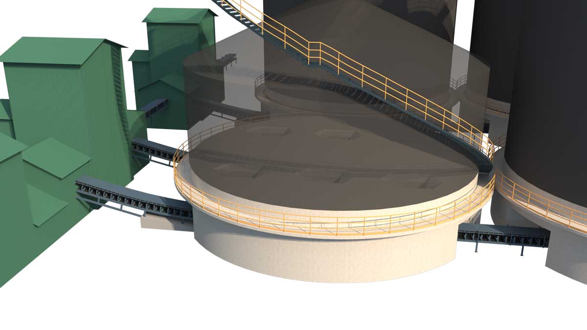
Rational Partitioning of Aeration Zones at the Silo Bottom to Enhance Cement Flowability
The partitioning of aeration zones at the silo bottom is a critical aspect of the discharge system design for large-scale welded steel silos. Its primary function is to improve the flow characteristics of cement particles by supplying low-pressure air to specific areas, thereby facilitating the smooth movement of material toward the discharge outlet.
1. Defining Aeration Zones Based on Silo Bottom Structure
For large-scale steel cement silos, the layout of aeration zones should be determined by considering factors such as the silo diameter, the slope of the silo bottom, the location of discharge outlets, and the specific properties of the material. A common design approach involves dividing the silo bottom into several relatively independent aeration zones, each equipped with its own dedicated air supply branch and control valve.
During the discharge process, one or more aeration zones can be activated as needed, allowing cement from different locations to gradually enter the flow stream and minimizing the risk of localized material stagnation.
Rather than relying on a simple, uniform division, the partitioning of aeration zones should be optimized based on the geometry of the silo bottom, the material flow paths, and the arrangement of discharge outlets. For large-capacity silos, particular attention must be paid to areas distant from the discharge outlets to ensure they receive adequate aeration coverage.
2. Optimizing the Cement Silo Aeration System
A cement silo aeration system typically consists of air compression or supply equipment, filtration units, piping, pressure regulation devices, control valves, and aeration elements (permeable components) located at the silo bottom. The system must deliver a stable, clean air supply that meets design specifications, ensuring that each aeration zone receives the appropriate volume and pressure of air.
Insufficient air pressure may prevent effective fluidization in certain zones, while excessive air supply can lead to unnecessary energy consumption and compromise the stability of material flow. Therefore, air supply parameters should be determined based on the resistance of the aeration elements, the layout of the silo bottom, and the characteristics of the cement—rather than simply increasing the pressure of the air blower.
Furthermore, the aeration elements must possess good permeability and durability; they should be inspected regularly for issues such as clogging, wear, or uneven air distribution.
3. Implementing Independent Control of Aeration Zones
Large-scale cement silos can utilize a zoned valve control system, allowing for the adjustment of air supply sequences across different areas based on material levels, discharge status, and operational requirements. For projects equipped with automation, this can be further enhanced by integrating pressure monitoring, valve status, and operational signals from conveying equipment to enable coordinated, zone-based control.
It is important to note that the primary function of an aeration system is to improve the flowability of the cement, rather than using air pressure to forcibly push large volumes of material out of the silo. Reliable discharge performance is achieved through a combination of optimal aeration intensity and a robust mechanical structure.
The value of zoned aeration is ultimately validated by the efficiency of material evacuation once the system is in operation. A case in point is the project delivered by SRON in the Philippines, which consists of ten 10,000-ton welded steel silos for cement and clinker. These silos feature a zoned aeration discharge system, integrated into a unified process chain alongside homogenization and elevation systems. Following commissioning, the project demonstrated a high material evacuation rate with virtually no residual material left inside the silos. For large-scale cement storage facilities, the ability to “empty the silo completely” is just as critical as “maximizing storage capacity.” Effective zoned aeration minimizes “dead zones” at the silo floor and significantly reduces the need for manual cleaning later on.
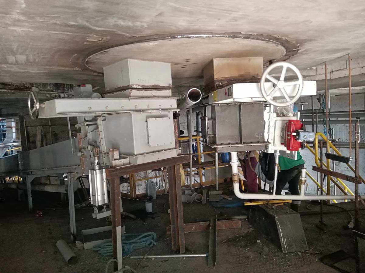
Utilizing a multi-point discharge design helps minimize material accumulation and eliminates “dead zones” during the unloading process
For large-scale steel cement silos, the strategic implementation of a multi-point discharge structure expands the effective discharge range and improves material flow across various areas of the silo floor.
1. Multi-point discharge improves material distribution
While traditional single-point discharge systems are structurally simple, they often struggle to facilitate the flow of cement located far from the discharge outlet, especially in silos with large diameters. A multi-point discharge system, by contrast, incorporates multiple outlets across the silo floor, arranged according to the silo’s dimensions and specific unloading requirements.
By coordinating the operation of these multiple outlets, the flow path for the material can be shortened, the risk of localized material accumulation reduced, and the continuous discharge capacity of large cement silos enhanced.
However, more outlets do not necessarily equate to better performance. The number, placement, and dimensions of the discharge outlets must be determined by carefully considering the silo structure, the slope of the silo floor, the configuration of aeration zones, and the layout of downstream conveying equipment.
2. Optimizing discharge sequence and flow distribution
In cement silos equipped with multiple discharge outlets, control strategies such as grouped activation, sequential switching, or coordinated operation can be employed. By regulating the activation status of each outlet, cement from different areas can be drawn out progressively, preventing excessive, concentrated discharge from any single zone.
If multiple outlets are connected to the same conveying system, it is also essential to ensure a balanced flow across the various branches; this prevents any single outlet from discharging at an excessive rate, which could otherwise overload the downstream conveying equipment.
Furthermore, a multi-point discharge design should be integrated with the silo floor’s aeration zones. By effectively coordinating the operation of these aeration zones with the discharge outlets, operators can minimize dead zones on the silo floor, improve material recovery rates, and reduce the frequency with which manual silo cleaning is required.
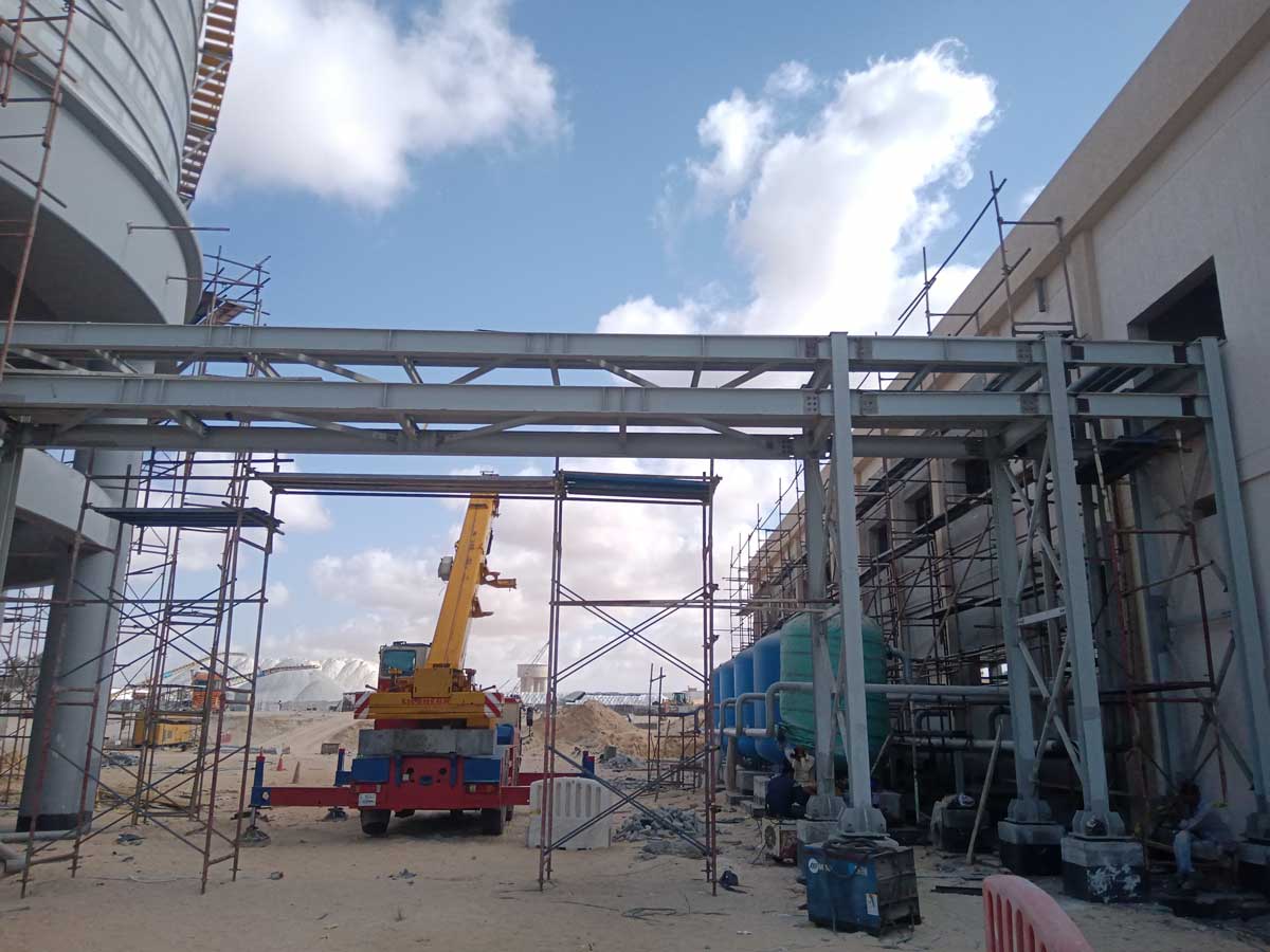
Achieving Continuous, Low-Resistance Conveying with Air-Gravity Chutes
Air-gravity chutes are commonly used for transporting cement and other dry, powdery materials. They are widely applied in systems such as bottom discharge for steel cement silos, clinker grinding circuits, and cement dispatch facilities.
Their operating principle involves using a permeable layer (aeration medium) to distribute air evenly throughout the material bed. This transforms the cement particles into a fluid-like gas-solid mixture; gravity, combined with the incline of the chute, then facilitates the continuous transport of the material.
1. Optimizing the Incline and Length of Air-Gravity Chutes
The conveying capacity of an air-gravity chute is closely linked to its incline, effective width, length, material characteristics, and air supply conditions. An insufficient incline may hinder material flow, while an excessive incline requires careful evaluation of available space, flow velocity control, and downstream interface requirements.
Therefore, for large-scale cement silo projects, the dimensions of the air-gravity chutes should be determined based on actual discharge requirements and site-specific spatial constraints, rather than relying solely on empirical estimates.
2. Ensuring Uniform Air Supply to Prevent Localized Blockages
The permeable layer of an air-gravity chute must maintain consistent air permeability. Uneven air supply, clogging of the permeable layer, or abnormal moisture content in the material can lead to restricted flow in certain areas and a reduction in overall conveying capacity.
During routine operation, it is essential to monitor air supply pressure, the condition of the permeable layer, the integrity of the chute seals, and the exhaust paths, while performing timely maintenance based on actual operating conditions.
3. Strengthening the Integration of Air-Gravity Chutes with Discharge Outlets
In systems with multiple discharge points, material from various outlets is typically channeled into one or more air-gravity chutes. In such configurations, careful attention must be paid to the material entry points, the convergence layout, and the space required for maintenance. This helps prevent concentrated material impact at a single location and avoids blockages caused by uneven flow distribution.
For projects involving long-distance transport or high throughput, it is also necessary to evaluate whether to implement segmented conveying, incorporate intermediate transfer equipment, or utilize other auxiliary transport methods.
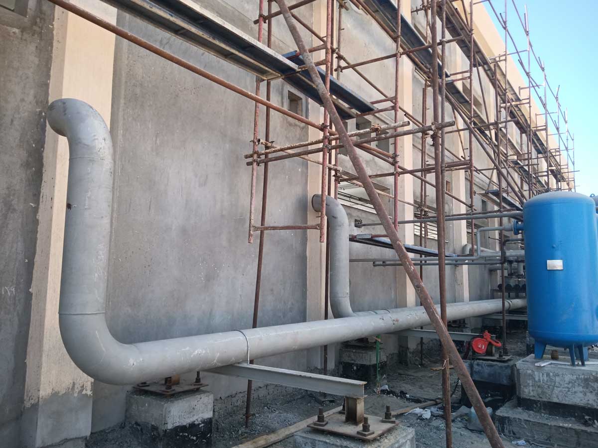
Ensuring Alignment Between Cement Silo Discharge Capacity and the Conveying System
The degree of alignment between a cement silo’s discharge capacity and its conveying system directly impacts the stability of the entire storage and transport operation. Even with effective aeration at the silo bottom and a well-planned discharge outlet layout, the system will fail to achieve consistent, high-efficiency operation if the downstream conveying equipment lacks sufficient capacity.
1. Determining Discharge Capacity Based on Actual Requirements
During the system design phase, it is essential to define the target discharge volume, peak dispatch requirements, continuous operating duration, and the intake capacity of downstream equipment.
It should be noted that the design discharge capacity of a cement silo should not be based solely on the theoretical flow rate of an individual outlet. Instead, it must account for the actual operating conditions of multiple discharge points, aeration efficiency, material characteristics, and capacity losses that occur during the conveying process.
2. Calculating the Processing Capacity of Equipment at Every Stage
A cement silo discharge system may comprise various components, such as silo-bottom discharge devices, air-gravity chutes (air slides), bucket elevators, screw conveyors, pneumatic conveying systems, and equipment for bagging or bulk loading.
During design, the processing capacity of each piece of equipment must be calculated stage by stage to ensure that the system’s continuous conveying capacity meets the target requirements. In a series-configured system, the capacity of the weakest critical component often acts as the primary constraint on the overall system performance.
For instance, if a cement silo requires continuous high-flow discharge, but the air-gravity chutes or elevating equipment have a low rated capacity, the system’s full potential cannot be realized—regardless of how high the discharge capacity at the silo bottom may be.
Engineering experience shows that issues in discharge systems often arise not at the silo bottom itself, but at the “interface” between the silo-bottom discharge and the conveying system. Specific points—such as discharge outlet openings, convergence points in air-gravity chutes, and the inlets of bucket elevators—frequently become bottlenecks after commissioning. Conducting thorough, stage-by-stage capacity calculations during the design phase is far more cost-effective than attempting to rectify these issues after the system is already in operation.
3. Implementing Robust Interlocks and Monitoring Mechanisms
An automated control system can be used to monitor the operational status of conveying equipment, material levels at critical points, air supply pressure, and fault signals from associated machinery. In the event of a downstream equipment failure or an anomaly within the transport path, the system should—based on its control logic—promptly restrict or halt the upstream supply of materials to prevent them from continuing to enter the affected area.
Implementing appropriate start-stop sequences, equipment interlocks, and anomaly alarms helps mitigate the risks of material blockages, spillage, and unplanned downtime, thereby enhancing overall operational reliability.
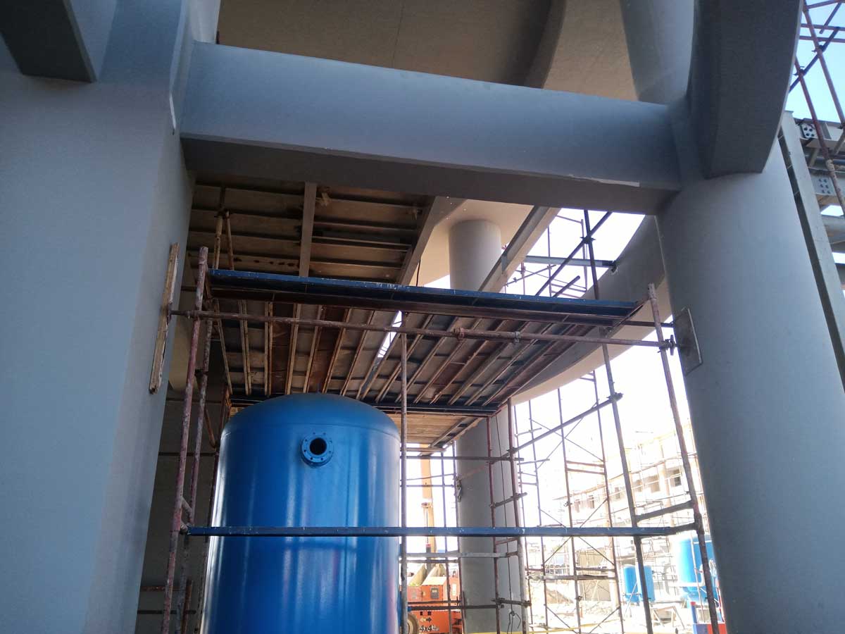
Optimizing Operation and Maintenance for Long-Term, Stable Discharge
The discharge performance of large-scale steel cement silos depends not only on the initial design but also, to a significant extent, on routine maintenance.
First, the aeration components at the silo bottom, air supply piping, and control valves should be inspected regularly. It is essential to ensure proper air supply to each zone and promptly address issues such as clogged aeration media or leaks in the piping.
Second, close attention should be paid to the storage duration, moisture content, and potential clumping of the cement. Maintaining the integrity of the silo’s seals and implementing effective moisture-proofing measures will help mitigate the risk of impaired material flow during discharge.
Furthermore, the aeration media, sealing structures, and connection points of the air-gravity chutes (air slides) should be inspected periodically. Simultaneously, the operating current, vibration levels, and throughput of the conveying equipment should be monitored. If a sustained decline in discharge volume is observed, a systematic investigation—covering the aeration system, material accumulation at the silo bottom, the condition of the discharge outlets, and the capacity of downstream conveying equipment—should be conducted, rather than simply increasing the air supply.
For cement storage and transport facilities in long-term, continuous operation, establishing detailed operational records and a preventive maintenance plan helps identify potential faults early, thereby reducing production losses caused by unexpected downtime.
| Component/Stage | Function | Design Considerations |
|---|---|---|
| Silo-Bottom Aeration Zoning | Improves cement flowability and reduces material retention | Divide zones based on silo-bottom geometry and discharge outlet layout (non-uniform segmentation); pay special attention to areas distant from the discharge outlets |
| Aeration System | Supplies stable, clean, low-pressure air | Determine air supply parameters based on the resistance of aeration components and material characteristics; conduct regular inspections for blockages and wear |
| Multi-Point Discharge | Expands the effective discharge range and minimizes “dead zones” | Determine the number and placement of outlets based on structural requirements; implement grouped activation and sequential switching to balance flow rates |
| Air-Gravity Conveyor (Air Slide) | Provides continuous, low-resistance transport of dry powdered materials | Design the inclination angle and length according to the required discharge capacity; ensure uniform air supply; pay close attention to the integration of multiple convergence points |
| Capacity Matching and Interlocking | Ensures continuous, efficient system operation | Calculate and verify the capacity of each piece of equipment; establish start-stop sequences, system interlocks, and alarms for abnormal conditions |
Frequently Asked Questions (FAQ)
Q1: What are the primary reasons for poor discharge from large-scale steel cement silos?
There are four common causes: moisture absorption and clumping of the cement (reducing flowability), the formation of stagnant zones due to single-point discharge, insufficient aeration coverage or uneven air supply at the silo bottom, and a mismatch in the capacity of downstream conveying equipment. Troubleshooting should systematically address these four areas, rather than simply increasing the air supply.
Q2: Does the aeration system at the silo bottom “blow” the cement out of the silo?
No. The function of the aeration system is to improve the flow state of cement particles (fluidization) using low-pressure air, allowing the material to flow smoothly toward the discharge outlet under the influence of gravity—it does not rely on air pressure to push the material out directly. Excessive air supply actually increases energy consumption and compromises flow stability.
Q3: Is it better to have as many discharge outlets as possible in a multi-point discharge system?
No. The number, location, and size of discharge outlets must be determined based on the silo structure, the slope of the silo bottom, the aeration zoning, and the layout of the conveying equipment. An excessive number of outlets increases structural and valve costs and makes it more difficult to balance the flow distribution across different branches.
Q4: How is the inclination angle of an air-gravity chute (air slide) determined?
The inclination angle is closely related to conveying capacity, chute width and length, material characteristics, and air supply conditions. It should be designed based on the actual discharge volume and available on-site space. For powdered cement, a shallow (gentle) inclination is typically used; one should avoid relying solely on empirical estimates.
Q5: How is the design discharge capacity of a cement silo determined?
It cannot be based solely on the theoretical flow rate of a single discharge outlet. Instead, it must account for the actual operating conditions of multiple discharge points, aeration effectiveness, material properties, and conveying losses. Furthermore, the capacities of all equipment in the series must be calculated, with the system’s overall capacity constrained by the weakest critical component.
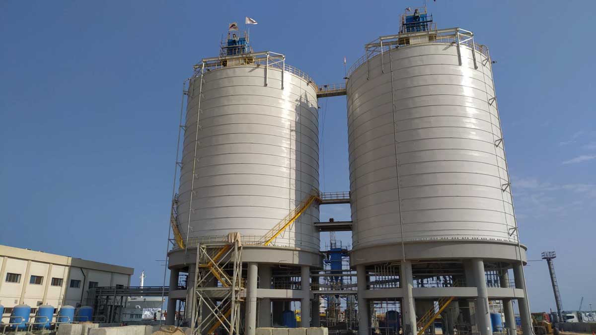
Achieving stable and efficient discharge from large-scale steel silos for cement storage does not depend on enhancing the performance of any single piece of equipment; rather, it requires the establishment of a well-coordinated, integrated discharge system. By strategically zoning the aeration system at the silo base, optimizing the cement aeration network, implementing an appropriate multi-point discharge configuration, integrating compatible air-gravity chutes, and ensuring that the discharge capacity at the silo base aligns with the downstream conveying equipment, one can effectively improve cement flow, minimize localized material buildup and transport blockages, and enhance continuous discharge performance.
For cement plants, grinding stations, bulk cement transfer terminals, and large-scale building material storage and logistics projects, it is advisable to adopt proven industry solutions during the design phase of the steel silos. This involves incorporating the silo structure, aeration system, discharge mechanism, conveying equipment, and automated control systems into a unified, comprehensive plan. Only by designing and optimizing from the perspective of the entire process can one ensure operational reliability, maximize the utilization of storage facilities, reduce maintenance costs, and meet the modern cement industry’s demands for efficient, continuous, and stable production. If you are currently planning a cement storage and dispatch system, please feel free to contact us for tailored recommendations on discharge solutions.